By Mr. Luis Fernandez Sanchez-Troche as (mis)interpreted by the webmaster
Last updated 03 October 2010
Group discussions
This article will try to
describe in a brief and chronological way the series of events that led to the
standardization of the first U.S. flight jet helmet. Due the complexity and
extension of the subject only the key elements are mentioned. This article does
not pretend to discuss every aspect; this will need to be addressed in another
forum.
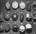
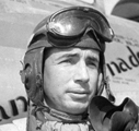
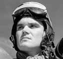
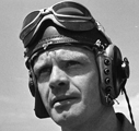
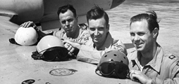
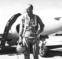
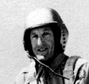
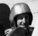
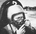
A range of pictures illustrating some of
the different helmet designs used for protecting pilots' heads during the early
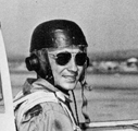
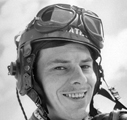
days of jet flight. Far left: P-80 test pilot Capt. Martin L. Smith from
the Flight Test Division at Wright Field was one of three pilots who
participated in the transcontinental speed run (L.A. to N.Y.) on 28
January 1946. Posing before departure, he is wearing a British
WWII glider helmet based on the Type C. Left: Col. David C. Schilling
during his command of the 31st Fighter Escort Wing in F-84G 51-1058. He
is wearing a modified U.S. Army M-1 infantry helmet liner (micarta
material - not the 'steel pot' portion) over what appears to be the
American Style "D" experimental summer flying cloth helmet. Middle: Eugene 'Gene' May, chief test pilot of Douglas
Aircraft Corporation, wearing a 'pudding basin' helmet. The 'pudding
basin' designation is just a description based on its appearance, not an
official one. Right: Lockheed test pilot, Anthony 'Tony' LeVier,
wearing what appears to be a British Type C helmet with a 'pudding
basin' hard top attached to it. Far right: Helmets on
their hooks at the 1st Fighter Group, March Field, California, October 1946. A
number of different designs are evident.
Pictures are © USAF, unknown, unknown, NASM and Life Magazine.
To unfold the information
is necessary to understand the role of the Personal Equipment Laboratory (PEL),
Clothing Branch, under the umbrella of the Engineering Division of the Material
Command in Wright Field (Wright-Patterson AFB, Dayton, Ohio). PEL was organized
in April 13, 1944 under the direction of Col. Millard Haskins, and was generally
responsible for the personal equipment for the AAF personnel. They designed,
tested and developed aircrew clothing, for their safety, efficiency and comfort
in all combat theatres of operations. In conjunction with other service
organizations such as the Aero Medical Laboratory (AML) and the Army Air Force
Board, Orlando, Florida, they developed and tested different flying helmets
which eventually led to the standardization of the P-1 flying helmet.
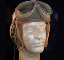
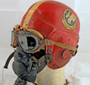
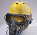
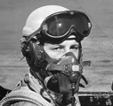
One of the interim solutions to the head
protection problem was simply to use Army tanker helmets without any
modifications except adding studs for oxygen mask attachment. Far left and
left: M-1938 tanker helmet. Middle, right and far right: USAF F-80
pilots wearing tanker helmets of slightly different configuration. The one on
the left is an M-1938. © unknown, unknown, Life, Life and Life.
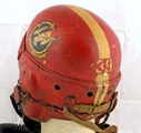
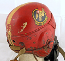
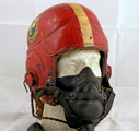
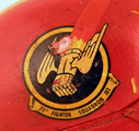
Another interim solution was to use modified leather football helmets like this
Wilson helmet painted in the colours of 71st Fighter Squadron, 1st Fighter
Group, March Field, California. It shows signs of having had a yellow crown
before the red paint was applied. Most likely its owner was part of the transfer
when 445th FS, 412th FG, was renamed 71st FS, 1st FG on 3 July 1946 and changed
its squadron colour from yellow to red in the process. Please note that the
pilot number "39" is visible under the red paint on the middle picture
immediately above the strap holding the goggle strap © Bluelight.
The concern to provide head protection during aircraft emergency landing existed before PEL was formed. One of many suggestions was address on the letter of May 21, 1943 by Air Corps 2nd Lt. Howard C. Gebel of the 398th Bombardment Squadron (M) 21st Bombardment Group at Mac Dill Field, Tampa, Florida to the AAF Material Center, Experimental Laboratory at Wright Field. This letter suggested the development of a crash crew helmet that could be donned quickly over the aircrew head in case of an aircraft emergency landing. The PEL were already conducting experiments to protect aircrew heads. Among this were the mask and helmet combinations. Type G-2, A-11, A-12, C-1 to mention a few. Private companies such as Consolidated Vultee Aircraft Corporation in San Diego, California were conducting experiments. By May 1944 they had designed the Crash Mask which was tested by the PEL but as many others it did not succeed.
Modified tank helmet
On April 19, 1945 Air
Corps Maj. Carl Arnold of the TSEAL-5C (Clothing Branch) were requesting tank
helmets, ordnance G-9, for PEL. They were an interim measure to be used for
developmental work for use as crash helmets for the Air Corps. On May 10, 1945
forty tanks helmets were shipped for modifications. The development work on
crash helmets (modified G-9 tank helmets) for use in the Lockheed XP-80 project
was accomplished by the PEL in conjunction with the plastic division of the
Continental Can Company, Inc. Chicago, Illinois. On January 8, 1946 a report
from the AAF Board did not recommend the modified tank helmet for
standardization but it continued in service for a while yet until replacements
were available.
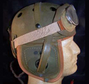
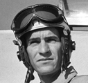
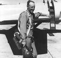
Far left: 1.Lt William Ross, 1st
Fighter Group, wearing a modified tank helmet worn over an AN-H-15 cloth helmet.
Left: Capt. John S. Babel from 412th Fighter Group, was another of the
three pilots who participated in the transcontinental speed run on 28 January
1946. He is wearing a modified tank helmet
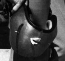
made by a rigger at Muroc. Middle: Capt. John Babel's helmet is now part
of the National Air and Space Museum collection. Right: Major G.I.
Ruddell, 1st Fighter Group, wearing a modified tank helmet worn over an AN-H-15
cloth helmet. Far right: Chuck Yeager at Wright Field wearing a modified
tank helmet over an A-11 leather helmet. © Life, Lockheed Corp., NASM, Life and Chuck
Yeager.
The authority for designing and developing a crash helmet was contained in the Technical Instructions No.2021, Add. No. 5, dated 8 May 1945, subject "Protective Helmet for Fighter Aircraft Pilots" and Directive from Headquarters AAF, AC/AS-4 dated 5 December 1945 with the same subject. A priority 1-C was assigned to this project. Expected service life of the shell was three years and the suspension assembly one year. A report of the first item designed under this project is contained in Proving Ground Command Project No. P7-45-25, subject: "Protective Helmet for Fighter Aircraft Pilots", dated 28 October 1945. The engineer responsible for the design and development of this item was Mr. W.L. Moore, Clothing Branch, Aero Medical Laboratory, Engineering Division, TSEAA-10. The estimated unit cost (including modification but less receivers) was approximately 30 dollars.
Style 1 helmet
By July 5, 1945 the Chief
of Material Division sent another developmental sample protective helmets
developed by Captain J.F. Hooper of the PEL to the AAF Board, Orlando, Florida.
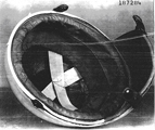
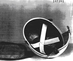
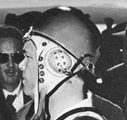
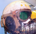
Prototype protective helmet developed by
Captain J.F. Hooper at the Materiel Division. The two pictures to the left
show the hard shell attached to a Type A-11 Intermediate Flying Helmet. The
three other pictures show the protective
hard shell giving details of the internal padding, strap suspension and the
attachment straps. All pictures are thumb-
nails ©
USAAF
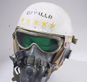
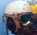
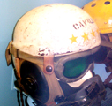
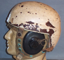
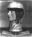
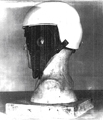
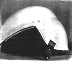
The first four pictures show a helmet that, according to the National Air and
Space Museum, was handmade by Stefan A. Cavallo, a test pilot for the NACA in
1944. Allegedly it was made from a fiberglass miner's hard hat attached to an
AN-H-15 summer flying helmet. The helmet is displayed at the NASM in Washington
DC, but due to glazing and light reflexes it is very difficult to take good
quality photos of it. It does transpire however, that Cavallo's helmet is almost
certainly an early version of the Style 1. Far right: Style 1
helmet in a privatel collection. Photos © NASM (far left) and G.M. Bell at
Bell's Aviation (the rest).
By October 1945 Mr. Lagrand Daly of the Paramount Rubber Company was sending another new type of helmet mould for evaluation at the PEL. As we can see many helmets were being tested at the same time by the PEL. Meanwhile by Oct. 31, 1945 Col. Haskins was sending a developmental helmet sample to the Chief Test Pilot, Jack Wodams of the Bell Aircraft Corporation in Buffalo, New York, for the XS-1 project. Also Tony LeVier, Chief Test Pilot of the Lockheed Aircraft Corporation in Burbank, California, received one.
In a letter of the 29
April 1946 the designation STYLE 1 was coined to the new helmet that the PEL has
developed (Although unconfirmed as of yet, it is believed that Hooper's helmet
was the one given the designation Style 1.). Seventy-five were forward to Randolph Field Texas for evaluation in
the P-80 type aircraft. Individual fitting of these helmets to students and
instructors range in head sizes from the smallest required size up to
approximately size 7-3/8 may be fitted. It is suggested the following method of
fitting be used in order to provide the greatest comfort and protection to each
individual.
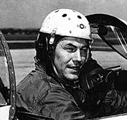
Far left and left: Capt. William
Gates, 36th Fighter Group, and Major Jay Robbins, 1st Fighter Group, wearing
Style 1 helmets over A-11 leather helmets. Middle: Three squadron
commanders from 1st Fighter Group. The two to the left have Style 1 helmets
while the pilot to the right has a modified tank helmet. Right: 1.Lt
Robert Drew, 1st Fighter Group, wearing a Style 1 helmet over an A-11 leather
helmet. All pictures are © Life.
With the standard flying helmet Specification No´s.3189 or 3230, properly fitted and adjusted to the individual’s head, place the protective helmet over the standard helmet.
- The protective helmet
should be adjusted so that the front edge of the crown is a low as possible
without interference with goggles.
- The edge of the protective helmet may be sprung to fit long narrow heads of
broad heads by pressing in the edges with the hands.
- Adjustment of the lacing cord inside the crown can be made to eliminate
interference of the back drop with the neck when looking upward or scanning.
- Adjustment of the headband to fit comfortably should be made by either
trimming a portion of the foam rubber padding from behind the sweatband for
larger heads, or inserting thin strips of felt behind the sweatband for smaller
heads.
- All adjustments must be made prior to installing attachment fastener to the
standard helmet. With both helmets in place and properly fitted, mark the under
helmet for stud fastener locations directly under the button fasteners, which
are the protective helmet attaching tabs.
- Removes the helmets from the head and install stud fasteners through the
helmet material at each of the four locations marked. Use stud fastener Part
No´s.AN227-8 and AN227-9; four each required per helmet.
- When installing fasteners on light weight helmets, insert chamois or light
weight leather reinforcement washers between the eyelet base and fabric.
The Bell Company were conducting a series of experiments with the XP-83 aircraft and made a series of recommendations by A.M. Johnston, Chief test pilot, to the Material Command (PEL) in modifying the Style 1 after an accident on Sept 4, 1946 by Mr. C.L. Fay. Among the recommendations were the built –in earphones, insufficient lamination in the helmet shell and a corner of approximately 70 degree angle in the crown and back drop edge. Because the Style B helmets were under development no changes would be done to the Style 1 helmet according to the reply from PEL.
Style B helmet
As mentioned above On January 8, 1946 a
report from the AAF Board did not recommend the modified tank helmet for
standardization. February 7, 1946 the PEL asked a number of companies to fabricate a helmet
(the one that would later be designated Style B) with the following
specifications:
a. Light in weight, less
than two (2) pounds, including accessories.
b. Coverage of the sides of the face and head approximately equal to the area
covered by a football helmet.
c. Fabricated from material with a breaking strength approaching 80 P.S.I. and
non-shatterable.
d. Side plates to be formed to include earphone mountings and earphones with the
cord lead entering the helmet just back of the right mounting.
e. A reinforcement on the frontal quarter of the outer shell, made from .020
Hatfield steel.
f. Adjustable webbing suspension for the back to top, with ventilated gores
passing through a non cellular, medium texture, sponge rubber which is to be
positioned between the sweat band and the shell.
g. Earphones mounting to be laced to leather inner cover to afford adjustment
characteristics, and to facilitate insertion of sponge plates behind the
earphones to meet individual requirements.
h. With adjustable chin strap that cups over the chin.
i. With durable dot stud fasteners on side plates to facilitate attaching the
oxygen mask.
j. Outside finish of helmet to be either metal sprayed and highly polished or
white durable enamel that will not chip or scratch with constant buffeting
against hard objects.
The approach was made to the following companies:
1- John T. Riddell, Inc.
1250 North Wood Street, Chicago, Illinois.
2- Strauss Company 1000 Ewart Building, Pittsburgh, Pennsylvania.
3- Paramount Rubber Company 10401 North Lawn Avenue Detroit, Michigan.
4- Amstrong Plastic Company 666 Lake Shore Drive, Chicago, Illinois.
5- Mine Safety Appliance Company 230 North Braddock Avenue, Pittsburgh,
Pennsylvania.
6- Continental Can Company, Inc. 231 East 95th street Chicago, Illinois.
7- Hawley Products Company of St. Charles, Illinois
Then by May 1946 a letter from the Headquarters of the Army Air Force, Office of the Air Surgeon, in Washington, D.C. to the Flying Safety Service, Langley Field, Virginia exist the concern about three P-80A aircraft accidents and if were related to head injuries that might occur at subsonic and transonic speed, especially in turbulent air. Letter also was sent to the Headquarters, Air Material, Command, Wright Field, Dayton, Ohio. A reply was given by Major General L.C. Craigies, Chief of the Engineering Division describing a new type of helmet STYLE B:
This new helmet has a
shell moulded from laminated 8 ounce enamelling duck impregnated with phenolic
resin. The shape is similar to that of a football helmet which provides maximum
coverage of the head, consistent with good visibility, head movements, goggle
type B-8 and oxygen mask integration. One size shell so far adequate for head
size up to 7-1/2.The design permits incorporating the headset with the side
flaps. Impact resistance of the shell is approximately 64 foot pound (falling
ball method). The outside surface is a metallic copper spray, applied by
scuffing the surface and painting with a mixture of clear lacquer and brilliant
copper flake powder, which has a high thermal insulation value. This finish is
easily scratched, but is not inclined to chip off as readily as the
electro-plated copper finish. Space within the helmet provide for air
circulation. The edge of the shell, has a plug strip of ¼ inch thick foam rubber
cemented to the inside adjacent to the edge, is bound with 1/8 inch diameter
rubber tube which has been split length-wise and a 1/32 inch thick strip of Buna
sheeting. Included in the binding around the corners of the flaps are
cut-to-shape neoprene sheeting for retaining the earphones mounting.
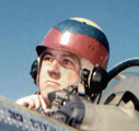
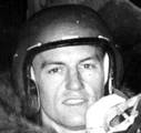
Colonel Albert Boyd (later major general),
commander of the Flight Test Division at Wright Field, Ohio, seen on 19 June 1947
after he set a new world speed record of 623.738 miles per hour in an XP-80R
over Muroc. Co. Boyd is wearing what is assumed to be a Style B helmet. Far
left: Col Boyd holding his helmet in his right hand. Left: Close-up
of the helmet from the first picture. Note the comm cord entering the helmet
immediately behind the right earphone as specified in subparagraph d. in PEL's
letter of 7 February 1946. Middle: Another view of Col. Boyd. The comm
cord with its PL-54 plug is hanging free from the helmet. Right: The
oxygen mask attachment studs are visible on the outside of the helmet shell on
both sides along the face opening. The helmet also has a chin strap with chin
cup. Far right: The angular shape of the helmet is notable in this photo,
as are the oxygen mask attachment studs. The metallic copper spray finish is
evident in both this picture and the one to the near left. All pictures © USAF.
Meanwhile Style 1 helmet will be used as an interim helmet besides being rejected in standardization test.
Following this incidents more than two hundred helmets [[the types not specified]] were issued to different government agencies for test.
On July 29, 1946 the PEL has already sent twelve Style B to the National Advisory Committee for Aeronautics (NACA) Office of Flying Safety, Langley, Virginia for preliminary test.
By 12 of December 1946 Dr. Charles Lombard, Department of Aviation Medicine, University of Southern California, Los Angeles, California already had designed and test a protective helmet for high speed aircraft pilot.
Style B-1 helmet
By July 29, 1947 the
Paramount Rubber Company was manufacturing the B-1 flying helmet. Despite the
fact that a test preliminary report had not been received from NACA, orders of
production and distribution had already started. Pre-standardization testing
would be conducted by Air Proving Ground Command, Florida and deliveries
expected to start approximately in July 15, 1947. The following military
installations received this helmet:
1. Williams Field,
Chandler, Arizona, Jet Training School
2. Langley Field, Hampton, Virginia, 363rd F.G.
3. March Field, Riverside, California, 1st F.G.
4. Selfridge Field, Mount Clemens, Michigan, 56th F.G.
5. Andrews Field, Washington D.C. 4th F.G.
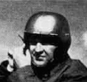
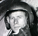
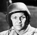
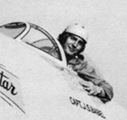
Pilots wearing what are believed to be Style
B-1 helmets - apparently the helmet that was standardised in September 1947 as
the P-1. All four helmets appear to have the same metallic copper spray finish
as the helmet worn by Col. Boyd. These helmets differ from Col. Boyd's by having
a sligtly rounder outline and leather oxygen mask tabs instead of the studs on
the helmet shell. Far left and left: US Navy pilots in what must be tests
of the new USAAF helmets. Middle and right: Don Hillman and G.I.
Ruddell of the 94th Fighter Squadron during P-80 cold weather trials at Ladd AFB.
Far right: Robert "Bob" Hoover climbing into a Mustang, 1948. Pictures far left and left © Naval
Aviation News, middle, right and far right unknown.
Due to the urgent requirement existing for head protection to pilots of high speed aircraft, this helmet was initially distributed to the AAF Fighter units. On 20 August of 1947 a letter was sent to the Commanding General, Army Air Force, Washington D.C., Research and Engineering Division from Colonel Arnold T. Johnson, Air Corps, Chief, Engineering Standards Sections, Engineering Division for the 'Authority for Change of Status of Equipment', now the P-1 [[Does this mean that the STYLE B-1 was standardised as the P-1? ]]. Standardization took effect on September 1947.
The Boeing Aircraft Company, Seattle, Washington is continuing testing the Lombard helmet in the XB-47 aircraft with pilots Robbins and Osler.
By November 12, 1947 the units listed below had already had Style B-1 helmets delivered as follows:
| 363rd Fighter Group | 25 Jul 1947 | 5 | |
| - | 15 Sep 1947 | 9 | |
| - | 6 Oct 1947 | 40 | |
| 1st Fighter Group | 29 Jul 1947 | 12 | |
| - | 18 Sep 1947 | 63 | |
| 4th Fighter Group | 1 July 1947 | 12 | |
| - | 15 Sep 1947 | 12 | |
| - | 23 Sep 1947 | 51 | |
| 56th Fighter Group | 31 Jul 1947 | 10 | |
| - | 15 Sep 1947 | 16 | |
| - | 29 Sep 1947 | 49 | |
| 14th Fighter Group | 9 Oct 1947 | 11 | |
| - | 27 Oct 1947 | 64 | |
| Jet Training School | 24 July 1947 | 5 | |
| - | 15 Aug 1947 | 20 | |
| Air Proving Ground Command | 15 Aug 1947 | 8 | |
| - | 10 Sep 1947 | 12 | |
| - | 10 Oct 1947 | 14 | |
| HQ USAF AC/AS-3 | 24 Jul 1947 | 3 | |
| BAGR (Navy) | 23 Jul 1947 | 2 | |
| Air Surgeon O., Genrl. Crow | 15 Sep 1947 | 1 | |
| NACA – Muroc, Calif | 15 Sep 1947 | 2 | |
| AAF Liaison, NACA, Moffett Fld | 10 Oct 1947 | 2 | |
| Air Materiel Command | |||
| - | TSFLT | 18 | |
| - | TSELC | 1 | |
| - | TSEEA-6, Vision Unit | 26 | |
| - | TSEEA-7, Bio-Physics, Anthropometric | 2 | |
| - | TSEEA-10, Display (Cycle Humidity Tested) | 1 | |
| - | Awaiting shipment | 9 | |
Eventually more helmets were shipped to other units. It is important to mention that not only the helmets where shipped but also questionnaires to evaluate this helmets.
By January 1948 Switlik Parachute Company, Trenton, New Jersey was awarded a contract to fabricate the P-1 helmet.
The P-1 helmet continued with improvements referred to a letter of June 8, 1948 from the 363rd Reconnaissance Wing in which it is stated that the oxygen mask attachments to these crash helmets were considered unsatisfactory for high altitude bailouts when the use of bail-out bottles was required. Beside every effort done at the AML in Wright-Patterson Air Force Base, to design and fabricate a protective helmet, the Headquarters, specifically the Air Surgeon’s Office, was still concerned about its capability to protect a pilot in the event of an ejection from a high performance aircraft.
In response and keeping with the assumption that the protective P-1 flying helmet would probably not stay on during bailout at high speed, the AML reply on a letter the 8 of December 1948 saying that is working with a helmet with attach front clear visor as well on the development of an under-helmet or harness which would be worn beneath the protective helmet and to which the oxygen mask would be attached. During dummy ejections with full gear it was demonstrated that the helmet with oxygen mask remained during all ejections.
Before this and demonstrating the pressure on the AML to put a satisfactory helmet in production, the AML issued a letter on August 9, 1948 in which they considered to contract for the design and construction of an experimental visor for attachment to the standard Pilot’s Protective Helmet. Among the companies who received such letters were:
1. West Coast Eng. Div.,
Co.
2. Gen. Mills. Corp., Mechanical Div.
3. Eastern Rotorcraft Co.
As a particular note, the foam sponge rubber identified on AF Drawing 47-R-3184 as U.S. Rubber Company’s Koylon use on the P-1 helmet is for pilot comfort, sound deadening and low specific gravity, not for shock absorbing properties.
A comparative service test was conducted on December 20, 1948 at the Air Proving Ground, Florida. This would help the Air Material Command to collect data and to establish the criteria essential to developing a better jet pilot helmet with particular attention to protecting the head and providing comfort to the aircrew. The helmets used for testing were:
a- P-1 (present U.S.
standard helmet)
b- Lombard (Protection, Inc.)
c- NAES Helmet (design at Naval Air Experimental Station) (H-1?)
d-Tuflite (Daniel Company)
The list below is a brief summary of the quantity and types of protective helmets issued and the using agencies around the end of 1947
|
QUANTITY |
TYPE |
AGENCY |
| 75 | Style 1 (Exp) | Jet Training Sch., Williams Field, Arizona |
| 35 | Style 1 (Exp) | 621st AFBU, Pinecastle AF, Fla. |
| 28 | Style 1 (Exp) | Fighter Flight Test, Wright Field, Ohio |
| 15 | Style 1 (Exp) | 412th Fighter Gp., FTB, Muroc, Calif. |
| 6 | Style 1 (Exp) | NACA, Langley Field, Va. |
| 13 | Style 1 (Exp) | SBAMA, San Bernardino, Calif. |
| 10 | Style 1 (Exp) | SAMA, McClellan Field, Calif. |
| 1 | Style 1 (Exp) | Bell Aircraft Corp. |
| 1 | Style B (Exp) | Office, Fly. Safety, Langley Fld, Va. |
| 1 | Style B (Exp) | Ground Forces, Fort Knox, Ky. |
| 54 | Style B-1 (ST) | 363rd Fighter Gp., Langley Fld, Va. |
| 75 | Style B-1 (ST) | 1st Fighter Gp., March Field, Calif. |
| 75 | Style B-1 (ST) | 4th Fighter Gp., Andrews Field, Wash.D.C. |
| 75 | Style B-1 (ST) | 56th Fighter Gp., Selfridge Fld, Mich. |
| 75 | Style B-1 (ST) | 14th Fighter Gp., Dow Field, Maine |
| 11 | Style B-1 (ST) | 20th Fighter Gp., Shaw Field, S.Carolina |
| 25 | Style B-1 (ST) | Jet Training Sch., Williams Fld, Arizona |
| 34 | Style B-1 (ST) | Air Proving Ground Command, Eglin Fld, Fla. |
| 3 | Style B-1 (ST) | Hq, USAF, Washington, D. C. |
| 2 | Style B-1 (ST) | U.S. Navy |
| 2 | Style B-1 (ST) | NACA, MAAF, Muroc, Calif. |
| 2 | Style B-1 (ST) | NACA, Moffett Field, Calif. |
| 3 | Style B-1 (ST) | Surgeon, Olmsted Field, Penna. |
| 1 | Style B-1 (ST) | Air Surgeon, Washington, D.C. |
| 20 | Style B-1 (ST) | Fighter Test, Wright Field, Ohio |